When people think about stealth aircraft, they usually picture sharp angles, matte black paint and dramatic silhouettes against the night sky. But what really keeps a platform off the radar screen is not aesthetics; it is math. Stealth is built on a set of quantifiable trade-offs that engineers can write into equations long before the first prototype ever flies.

In this article, we look at the mathematics behind low observability, focusing on radar cross section, shaping, materials and multi-spectral signatures. The goal is not to turn you into a radar engineer, but to show how much of “mystical stealth” is in fact a very grounded numbers game.
Low Observability: More Than “Invisible to Radar”
Stealth technology, or low observable technology, is not a single trick. It is a toolbox aimed at reducing how detectable a platform is across several parts of the spectrum, including radar, infrared, acoustic and sometimes even visual. In practice, however, the radar problem dominates the design conversation for modern aircraft and many missiles.
From a mathematical perspective, stealth does not aim for absolute invisibility. Instead, it tries to compress the detection window, shortening the distance and time in which an adversary’s sensors can achieve a confident track. If a hostile radar can only detect your aircraft at 40 kilometers instead of 200, you have fundamentally changed the engagement geometry even if you are never truly “invisible.” This is why so much of LO design is about controlling energy, not eliminating it. When a radar illuminates an aircraft, that energy has to go somewhere, and the designer’s job is to ensure that as little as possible goes straight back to the radar’s receiver.
Radar Cross Section: The Core Variable
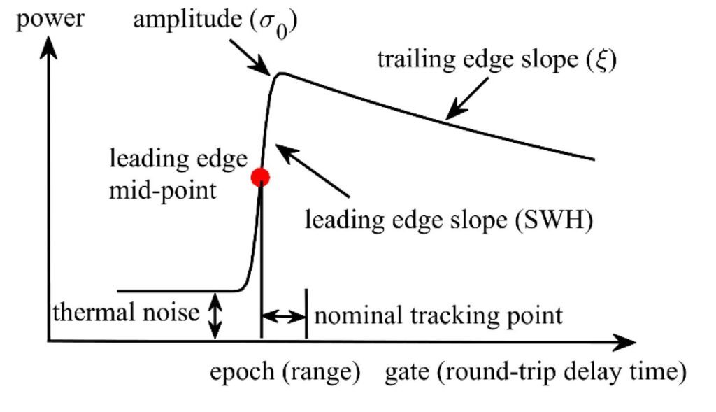
The central quantity in this conversation is Radar Cross Section, often denoted by σ and measured in square meters. RCS does not represent the physical size of an object. It represents the area of an equivalent ideal reflector that would send the same amount of energy back to the radar as the real target does.
To understand this, compare a metal sphere and a flat metal plate. A sphere reflects energy in a predictable way and its RCS can be estimated directly from its diameter. A flat plate, however, can appear far larger when it is oriented directly toward the radar. If tilted even slightly, it reflects energy away, and the RCS drops sharply. Stealth design relies heavily on this behavior. Instead of trying to shrink the aircraft physically, engineers shape it so that radar sees something far smaller.
The Radar Range Equation: Why Small Changes Matter
The radar range equation shows how detection range depends on RCS. In simplified form, maximum detection range is proportional to the fourth root of the RCS. This relationship often surprises people. Reducing RCS by a factor of 10,000 does not reduce detection range by the same amount. Instead, the reduction is around a factor of 10 because of the fourth-root relationship.
This is precisely why stealth designers pursue dramatic RCS reductions. A platform with an RCS similar to a small bird instead of a metal aircraft does not disappear, but it forces the adversary into much shorter detection ranges where timing, weapon envelopes and command decisions become far more difficult. Operationally, this can shift a situation from comfortable tracking to barely achieving a lock.
Shaping: Redirecting Energy Instead of Absorbing It
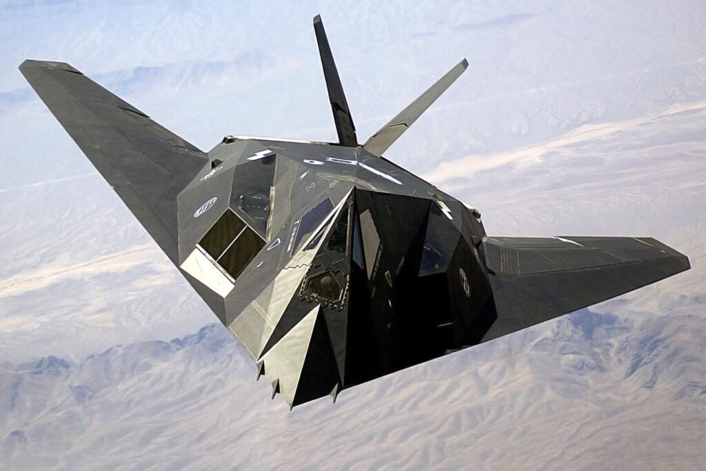
Shaping is the most visible tool in the stealth engineer’s arsenal. Surfaces, edges and volumes are arranged so radar energy scatters away rather than back toward its source. The early F-117 design illustrates this clearly: its faceted surfaces were laid out to send radar energy into empty space under most viewing angles. Coatings played a supporting role, but geometry did the heavy lifting.
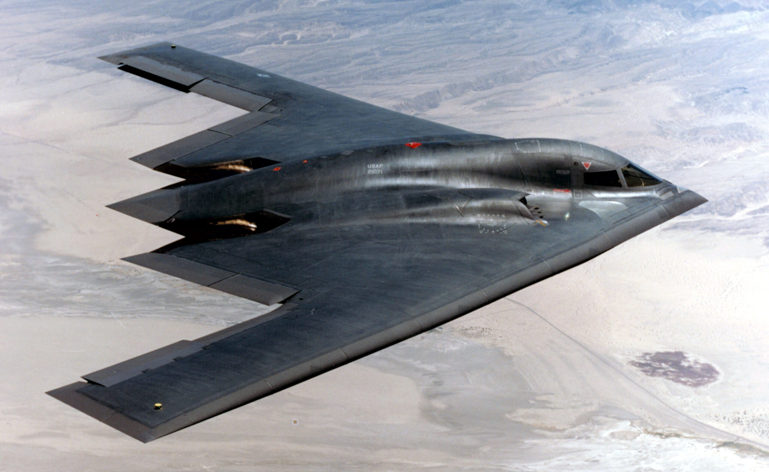
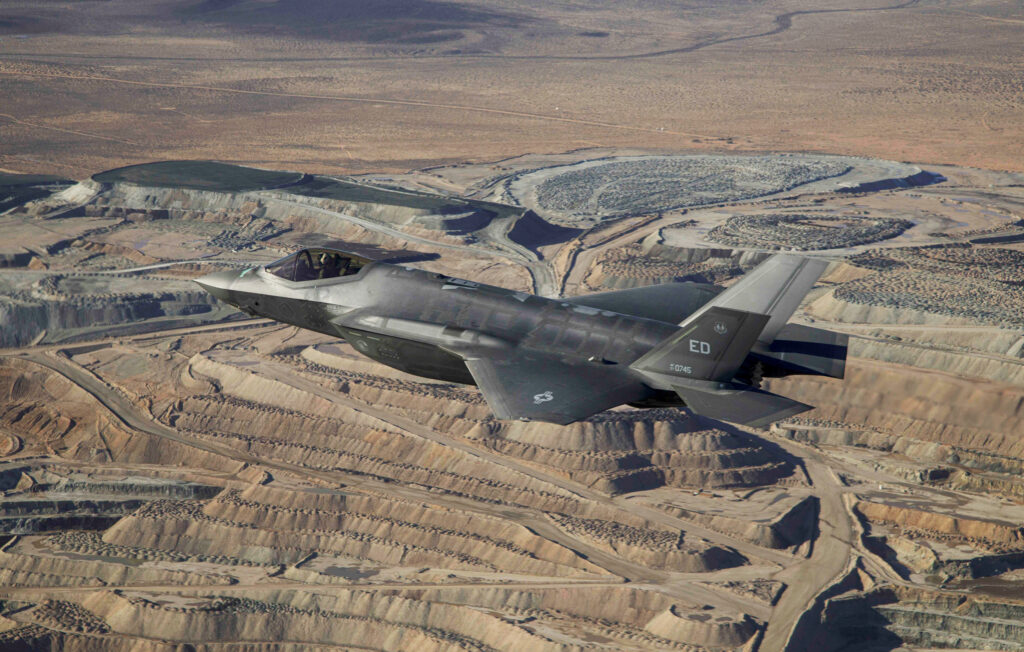
Later stealth aircraft such as the B-2 and modern fighters replaced hard facets with smooth, blended curves. Their airframes align edges, bury engine inlets and avoid right-angle junctions that behave like radar mirrors. Technical work from NATO and other research centers shows how even small details such as panel edges, antenna mounts or access doors can introduce noticeable increases in signature if left uncontrolled.
Stealth shaping is ultimately a balance between competing requirements. A surface that is perfect for redirecting radar energy may be terrible for lift or cause structural stress. Designers must negotiate between aerodynamics, structural loads, internal volume and electromagnetic behavior.
Materials and Coatings: Absorbing What You Cannot Redirect
Shaping cannot solve every problem. Radar-absorbent materials and coatings introduce controlled losses by converting part of the incoming electromagnetic energy into heat. These materials may use conductive fillers, magnetic particles or engineered microstructures to absorb specific radar frequencies.
The F-117, for example, combined its faceted shape with a full suite of coatings to ensure reflections remained below detection thresholds in key radar bands. These coatings were not decorative; they were deeply integrated with expected threat frequencies and operational environments.
Modern research into metamaterials and metasurfaces has broadened the toolkit. Instead of merely absorbing energy, some patterns can steer scattering in tailored ways, offering designers the ability to fine-tune radar behavior without major structural changes. At the mathematical level, all of this becomes a problem of impedance matching, resonant effects and wave interactions, but operationally it boils down to whether the platform stays below detection limits when it matters.
Beyond Radar: Infrared and Acoustic Signatures
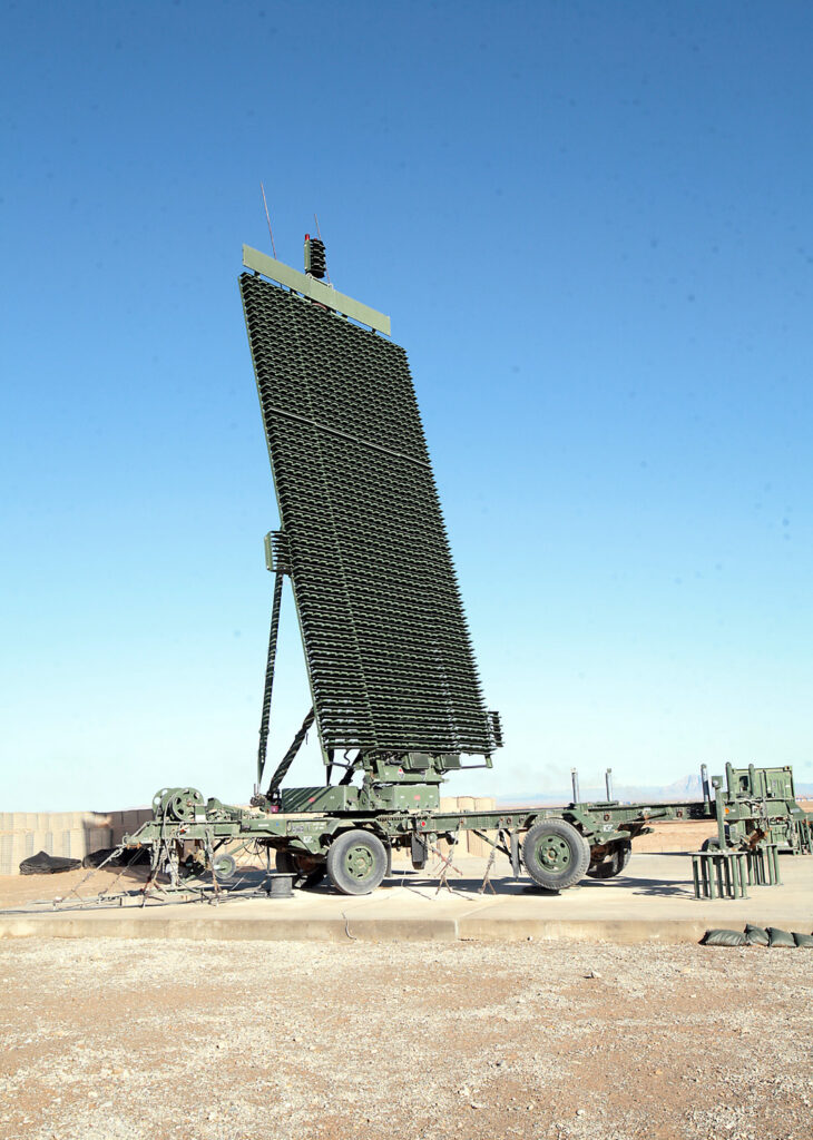
Stealth extends into infrared and acoustic management. Modern integrated air defense systems often combine radar, infrared tracking and passive RF sensors, making cross-spectrum signature management essential.
Infrared suppression follows the Stefan–Boltzmann law, where radiated energy increases with the fourth power of temperature. A modest reduction in exhaust temperature can dramatically decrease infrared output. Measures such as mixing hot exhaust with cool air, shielding the plume or using non-circular nozzles work precisely because of this mathematical relationship.
Acoustic stealth, especially in submarines and certain aircraft, involves vibration isolation, low-noise machinery and optimized propeller design. Instead of square meters and radar equations, engineers work with decibels, frequency bands and propagation models. But the philosophy remains similar: push the signal below background noise or sensor sensitivity.
Stealth as a Constantly Moving Target
The mathematics of stealth must evolve continuously. Radars improve, signal processing advances and new sensing modes appear. Threat radars increasingly use wide bandwidths, multi-static geometries and fused sensor data to expose targets designed for older radar generations.
For engineers and planners, this means stealth is not a fixed achievement but a constant process. A perfect signature reduction for today’s environment might degrade sharply against tomorrow’s sensors. Yet the underlying questions remain the same: how much energy reaches the target, how much returns to the radar, and at what distance does that return exceed noise?
Low observability is ultimately where physics, engineering and operational reality converge. Its mathematics is challenging, but its purpose is simple: shape the battle space by shaping what the enemy can see.
References
- Barton, D. K. (2011). “Radar Cross Section.” MIT Lincoln Laboratory – Radar Handbook Supplement
Massachusetts Institute of Technology. - Skolnik, M. (2008). Radar Handbook (3rd Edition).
McGraw-Hill Professional. - General Accounting Office (GAO). (1996). Aircraft Survivability: Reduction of Infrared Signatures in Tactical Aircraft.
GAO/NSIAD-96-72.